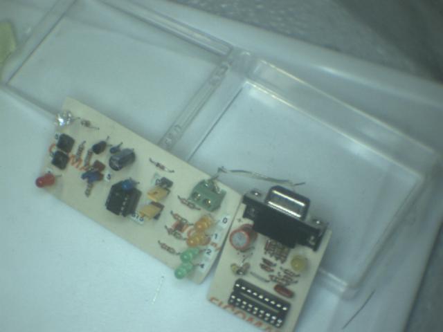
I used the cool FENG RCD programmer to program the 12F675 chips for even more fun, I built the 12F675 experimenter kit"
Though you can't quite tell from the picture, the four LED's to the right are, GP0, GP1, GP2 and GP4. Because GP3 can't be used as ouput, but either as /MCLR or INPUT only.
So GP3 is wired to a switch (labelled 3)
The clock source is the 4Mhz nominal internal clock, so I get to use GP5 as an I/O pin. On the left side of the board is a jumper that will select either the second switch (labelled 5) or the RED LED in the bottom left hand corner.
Since GP0 and GP1 can also be inputs in comparator modes, I have jumpers that switch them from LED OUPUTS to just an ouput that I can grab onto.
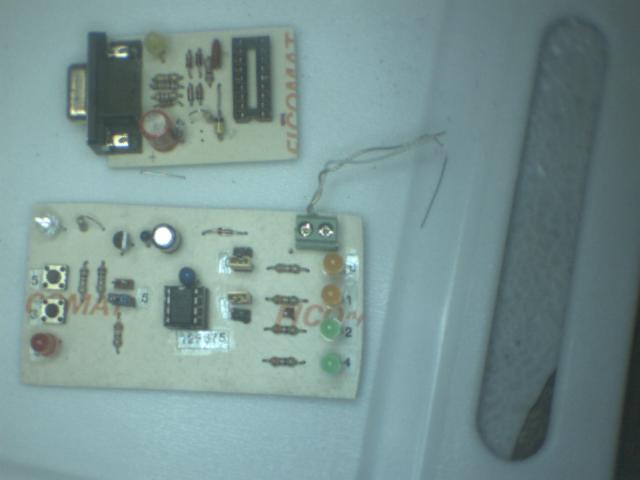
Another view, showing the Experimenter Board and RCD programmer