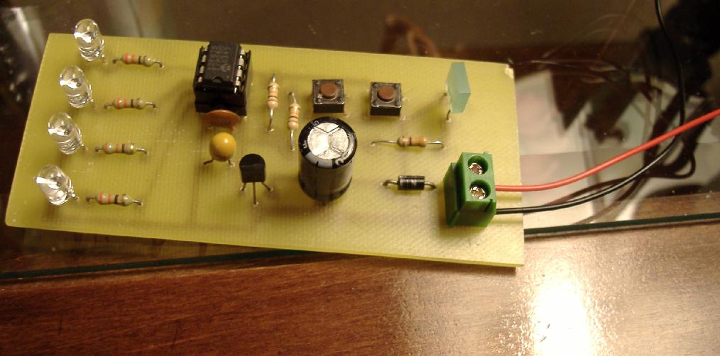
GP0, GP1, GP2, GP4 are all set as Digital Outputs
GP3 is wired to a NO switch pulled high via a 10K resistor
GP5 is wired similarly
The clock source is the 4Mhz nominal internal clock, so I get to use GP5 as an I/O pin.
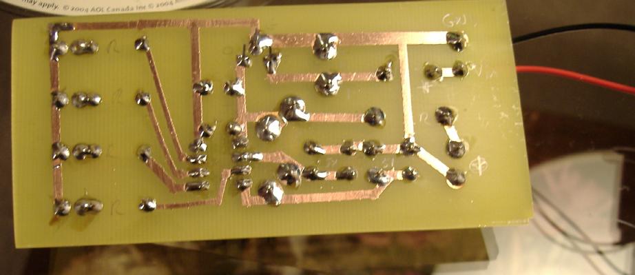
Another view, showing the pcb side